



How Servo Control Improves Bend Consistency in High-Volume Busbar Work
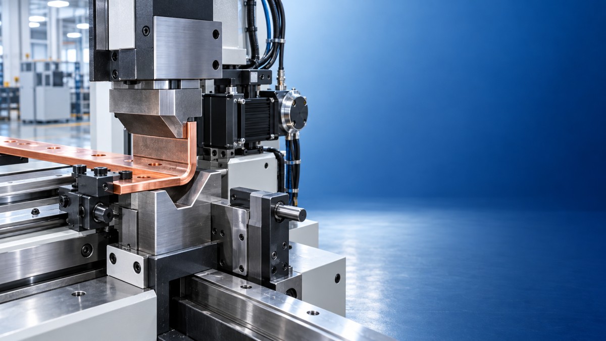
High-volume busbar bending becomes unstable when the machine treats every blank as if it has identical stiffness, thickness, and springback. Copper and aluminum conductors can look correct at the moment the punch reaches its programmed position, then relax to different final angles after pressure is released. A servo CNC busbar bending machine addresses this problem by controlling motion through measured position feedback rather than relying only on a fixed mechanical stroke.
For bend consistency, the useful result is not simply that the ram stops accurately. Servo control coordinates approach speed, forming speed, dwell, reversal, and final position so that the material is bent under repeatable conditions. This reduces variation between parts, particularly where a production run includes several bend angles, conductor widths, or material lots.
Position Feedback Changes the Bending Decision
In a conventional fixed-stroke arrangement, the forming position is set and repeated mechanically. Repeatability can be acceptable when material and tooling remain unchanged, but a small difference in actual thickness or hardness changes the relationship between ram travel and finished angle. A bend that is visually close to target may still create alignment problems at terminals, insulator supports, switchgear compartments, or laminated busbar assemblies.
A servo axis uses encoder feedback to compare commanded movement with actual axis position throughout the cycle. The controller can decelerate before contact, form at a controlled rate, reach a defined position, and return without relying on a sudden hydraulic stop. When the program includes the correct tool geometry and material condition, this motion control makes the final bend much less sensitive to cycle-to-cycle speed variation.
Servo positioning should not be confused with automatic correction of every angle error. The encoder confirms machine-axis position; it does not automatically know the finished angle unless the equipment also uses angle measurement or a validated compensation model. The distinction matters when reviewing process capability. Stable ram travel is evidence of controlled motion, while stable released angle requires confirmation on the formed workpiece.
Springback Must Be Managed as a Material Condition
Springback is one of the main reasons that identical programs can yield inconsistent busbar angles. After forming, elastic energy in the conductor causes the bend to open slightly. The amount changes with alloy condition, temper, cross-section, bending direction relative to grain, bend radius, and tool contact geometry. Aluminum and copper should therefore not be treated as interchangeable merely because their nominal dimensions match.
Servo control supports compensation by delivering a repeatable overbend position. A program can command the tooling past the required final angle so that springback returns the part to specification. The compensation value must be based on controlled trials using the actual bar stock and die set. Reusing a value from a narrower bar, a different temper, or a worn tool can create a systematic error that appears highly repeatable but remains out of tolerance.
Material variation within a delivery also deserves attention. A changed coil or bar batch may retain the same labeled grade and dimensions while responding differently during bending. When a first-off angle begins to drift after a material change, increasing pressure is not automatically the correct response. The observed condition could result from springback, incorrect material thickness entry, tooling setup, or a reference-position error. These causes leave different traces in the production record.
Controlled Speed Protects Both the Bend and the Tooling
High travel speed is valuable during non-forming movement, but it is not always suitable at tool contact. An aggressive impact can mark soft copper, shift a poorly supported bar, or create inconsistent seating against the back gauge. Servo programming allows a fast approach followed by a slower, controlled forming segment. The transition point should occur before the punch substantially loads the material, rather than after the bend has already started.
This profile is especially relevant on wide, thin, or long busbars. Such parts can flex before the intended bend line is fully established. If the workpiece is not supported consistently, the measured machine position may be correct while the physical bend location or flange geometry varies. Support arms, locating stops, clamping condition, and the flatness of the incoming bar must match the programmed setup.
A dwell at the formed position can be appropriate where the process requires the material to settle under load, but it is not a universal cure for springback. Extending dwell time without confirming the cause of angle variation slows output and may increase marking at the contact surface. Its value should be verified by comparing released angles across consecutive parts, not by judging the part while it remains under the punch.
Repeatability Depends on the Reference Chain
A servo system repeats what it is told to repeat. The entire reference chain must therefore be stable: program zero, machine home position, punch and die selection, back-gauge reference, material data, and part orientation. A minor offset at any of these points can produce a reliable but wrong result across an entire batch.
Tool identification is particularly important when multiple die radii are available. Changing the lower die opening alters the material support and the force path, which changes the resulting angle at a given ram position. A tool with a polished but altered contact profile can have the same part number as a new tool while producing different bend behavior. Tooling condition should be considered whenever a previously proven program begins to require repeated adjustment.
Production records are more useful when they separate axis-position observations from finished-part measurements. A stable servo position with drifting released angles points toward material, tooling, or clamping conditions. A drifting axis position or inconsistent return-to-reference result points toward the motion system, encoder reference, mechanical transmission, or program execution. Combining those signals prevents unnecessary changes to compensation settings.
Measurements That Reveal the Source of Variation
- Released bend angle: Measure after the part is fully unloaded and at a consistent inspection location. A reading taken too near a rounded corner can reflect local radius geometry rather than the true flange angle.
- Bend-line location: Confirm the distance from the bend to holes, end faces, and reference edges. Correct angle alone does not ensure fit-up when the bar has shifted against the locating system.
- Surface condition: Inspect for punch marks, cracking, edge distortion, and plating damage where applicable. These signs often appear before dimensional variation becomes severe.
- Program and tool traceability: Record the active program revision, die profile, punch profile, material designation, and compensation setting with the sample results.
Hole location adds another layer of control when punching and bending occur in the same route. A bend can be dimensionally correct yet still interfere with hardware if punched features were referenced from a different datum than the bending setup. The same principle applies when special punch tooling is introduced, such as Other-Special-Dies-punching: the formed part should be evaluated against the complete datum scheme rather than treating punching and bending as isolated checks.
When Servo Precision Does Not Solve the Problem
Servo control cannot compensate for poor die selection, burrs that prevent flat seating, contaminated contact surfaces, or a busbar placed against the wrong stop. It also cannot prevent cracking caused by a bend radius that is unsuitable for the conductor condition. A tightly controlled axis may repeatedly create the same defect when the process window itself is incorrect.
Angle inconsistency may also be mistaken for a machine problem when the inspection method is unstable. A hand-held protractor, an angle gauge placed across uneven surfaces, and measurements taken with varying flange support can disagree even when parts are consistent. The measurement device, contact points, and sampling position need a defined method. For parts with short flanges or complex offsets, a fixture that establishes the functional datum is more meaningful than a casual surface reading.
Maintenance affects consistency through mechanical condition as well as electronics. Loose tool holders, worn guide surfaces, backlash in transmission components, insufficient lubrication where specified, and movement in the back-gauge assembly can all undermine a carefully calibrated servo program. A return-to-home verification and a controlled trial piece after tooling changes provide a practical way to detect a broken reference before a large batch is processed.
Stable busbar bending comes from linking servo motion to verified material data, suitable tooling, fixed locating conditions, and measurement after springback. When those elements remain controlled, servo-driven forming turns angle compensation from repeated manual correction into a defined, traceable production parameter.
Send Us A Message
Get in Touch
*We respect your confidentiality and all information are protected.

First class quality service and professional after-sales team.