



Preventing Springback Errors on a Servo CNC Busbar Bending Machine
Springback occurs when a copper or aluminum busbar recovers part of its shape after the bending force is released. The programmed angle may be correct, yet the finished part opens beyond the intended angle. On a servo CNC busbar bending machine, the most reliable response is to treat springback as a controlled process variable: identify the material condition, establish a verified compensation value, and keep the bending setup stable from the first piece through production.
A small angle error can become a fitting problem when a busbar must align with insulated supports, switchgear terminals, enclosure clearances, or a parallel conductor path. Trying to correct each finished part by hand often creates further variation. The better approach is to make the machine repeat the same overbend under the same material and tooling conditions.
Start with the finished angle, not the displayed bend command
The servo axis controls ram position and bending movement with high repeatability, but position is not identical to the final unloaded angle. The program must include an overbend value that compensates for elastic recovery. For example, an inside bend intended to finish at a right angle may need to be formed slightly tighter before the tool retracts. The required amount is established by trial bends and measured after the material has fully released.
Do not create one universal compensation value for all busbars. A setting established on one batch can be wrong for another even when width and thickness appear identical. The final angle is influenced by the interaction between the workpiece, bending die, punch geometry, and machine sequence.
Separate material variation from positioning error
Two defects can look alike on a completed busbar. If every piece is consistently open by nearly the same amount, the likely issue is insufficient angle compensation, an incorrect tool selection, or an inaccurate reference angle in the program. If the angle varies from piece to piece, look first at material consistency, incomplete seating against the back gauge or stop, die movement, clamping condition, and lubrication or debris on the tooling surfaces.
Length-related errors should also be separated from springback. When the bend angle is acceptable but the leg length is wrong, changing angle compensation will not solve the problem. Check the datum edge, stop position, bend-line calculation, and whether the workpiece was seated flat before the cycle began. A busbar that shifts slightly as the punch engages can show both an angle error and a location error, but they need different corrections.
For parts with multiple bends, inspect each bend relative to the original reference face rather than judging only the final overall shape. The first bend may affect how the bar sits for the second bend. A minor opening at the first station can change the contact position at the next station and make the final error appear larger than the original springback.
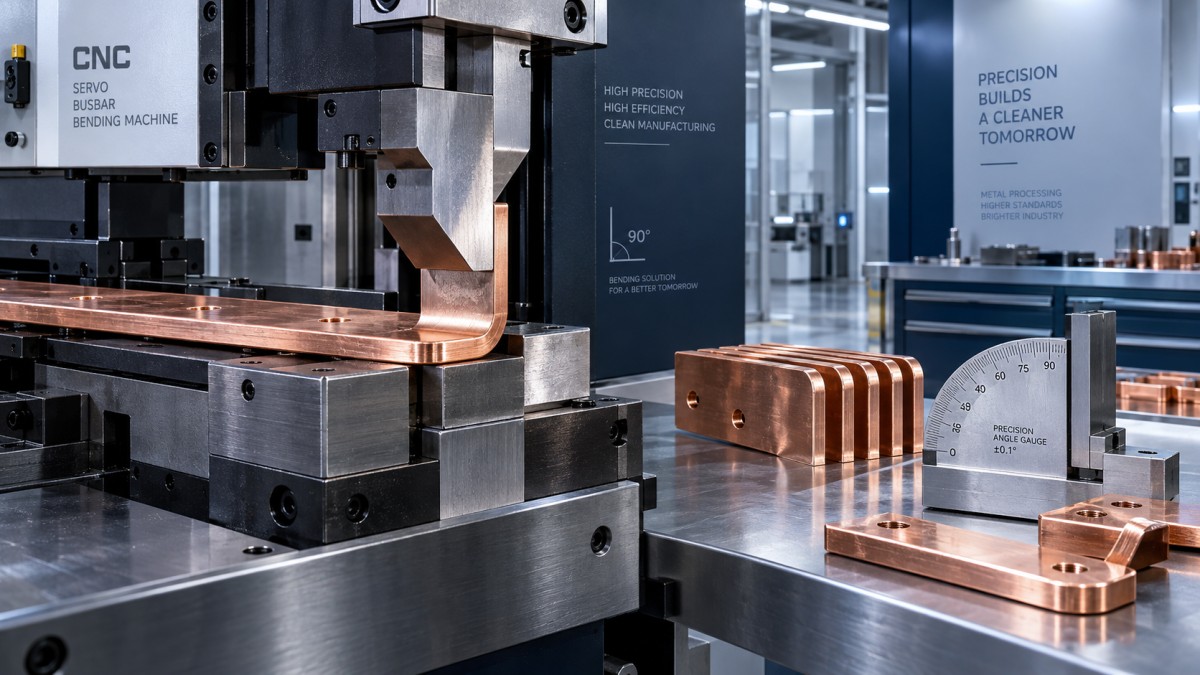
Build compensation from controlled sample bends
Use offcuts from the same stock intended for the job whenever possible. Material from a different coil, supplier, temper, or storage batch can react differently. Mark the sample with its material grade or condition, thickness, width, bending direction, tooling combination, and target angle. Those details make a compensation record useful later instead of turning it into an unexplained number in a program library.
Measure the angle after the ram has fully retracted and the part is resting without external force. A reliable angle gauge or dedicated fixture is preferable to estimating against a square, especially where the drawing permits only a narrow tolerance. Measure at more than one location across wide busbars. If the angle differs across the width, the problem is not simply a compensation value; it can indicate uneven tool contact, material twist, a misaligned die, or foreign material under the workpiece.
Adjust the program in small, deliberate increments. A large correction can overshoot the target and obscure the actual relationship between command angle and finished angle. Once the result reaches the drawing requirement, repeat the bend on additional samples. Repetition confirms that the setting is stable rather than accidentally correct on one piece.
Tool geometry sets the limits of a good program
Servo control cannot compensate for unsuitable tooling. The punch nose radius and die opening establish the inside radius and influence how strongly the material resists deformation. A radius that is too small for the material condition raises the risk of surface damage or cracking on the outside of the bend. A radius that is too large may produce a different final form than the installation requires and may increase uncertainty in angle recovery.
The die must support the busbar evenly. A worn edge, chipped corner, or uneven seating face can leave a witness mark and shift the effective bend line. Tooling should be clean, correctly oriented, and fully secured before samples are made. If a die is replaced after the program has been approved, validate the angle again; nominally similar tooling does not always create identical results.
Cut quality matters before bending begins. A heavy burr or distorted end can prevent the busbar from locating squarely against a stop, particularly on short legs. Where blank preparation requires a replacement cutting component, the relevant selection is a properly matched Cutting Die that produces a clean, repeatable edge for the specified busbar section. The purpose is accurate downstream location, not merely a visually neat cut.
Use the bending sequence to protect accuracy
For a part with closely spaced bends, choose a sequence that leaves adequate clearance for the formed section and keeps the reference surface accessible. Bending a short return first may make it difficult to position the longer section flat against the gauge later. The resulting angle deviation may be blamed on springback even though the workpiece was tilted during the second setup.
Keep the bending direction consistent when the drawing and part geometry allow it. Copper and aluminum stock can carry residual stress from rolling, leveling, or previous handling. Reversing orientation from one part to the next introduces an unnecessary variable. When a job requires bends in both directions, retain separate validated entries rather than assuming equal compensation in reverse.
Material temperature also deserves attention. Busbars stored in a cold area and processed immediately may not behave exactly like stock that has stabilized at the working area temperature. This is rarely the first cause to investigate, but it becomes relevant when a proven program begins drifting without a clear tooling or setup change.
When a previously stable program starts producing open bends
First inspect the actual die and punch rather than immediately increasing overbend. Check for loose fasteners, wear at the forming edges, damaged guide surfaces, accumulated copper or aluminum particles, and incorrect tool height. Confirm that the selected program matches the installed tooling and material thickness. Then check that the bending axis reaches the commanded position consistently and that reference procedures have been completed according to the machine's normal setup requirements.
Next, compare a new sample with an approved earlier piece. Look beyond the angle: inspect the inside radius, bend-line location, surface marks, and whether the bar sits flat. A changed radius or shifted bend line points toward tooling or positioning. A clean, correctly located bend that opens uniformly points more directly to material condition or an overbend value that no longer matches the stock.
Store the validated program with clear identifiers for material, thickness, width, die set, punch radius, target angle, and bend orientation. That record prevents a common production error: applying a compensation value from a visually similar busbar to a different forming condition. Springback becomes manageable when each correction is tied to the exact conditions that produced it.
Send Us A Message
Get in Touch
*We respect your confidentiality and all information are protected.

First class quality service and professional after-sales team.