



Punching and Shearing Busbars: Which Tolerances Matter in Switchgear Production?
Punching and Shearing Busbars: Which Tolerances Matter in Switchgear Production?
In switchgear production, a busbar can appear straightforward: cut it to length, make the required holes, bend it where needed, and install it. Yet many assembly delays and safety concerns begin with small dimensional deviations that were accepted too casually at the processing stage. A hole that is slightly displaced, a cut edge with excessive burr, or a twisted copper bar may still pass a quick visual check. Once it reaches a crowded panel, however, it can compromise alignment, clearances, joint contact, or installation time.
For quality-control and safety teams, the practical question is not whether every busbar must be made to the tightest conceivable tolerance. It is which tolerances affect the finished switchgear assembly, and how they should be controlled consistently. The answer depends on the bar size, material, joint design, enclosure layout, applicable project requirements, and the processing capability of the equipment. Still, several tolerance categories deserve attention in nearly every punching and shearing operation.
Hole Position: The Dimension That Controls Assembly
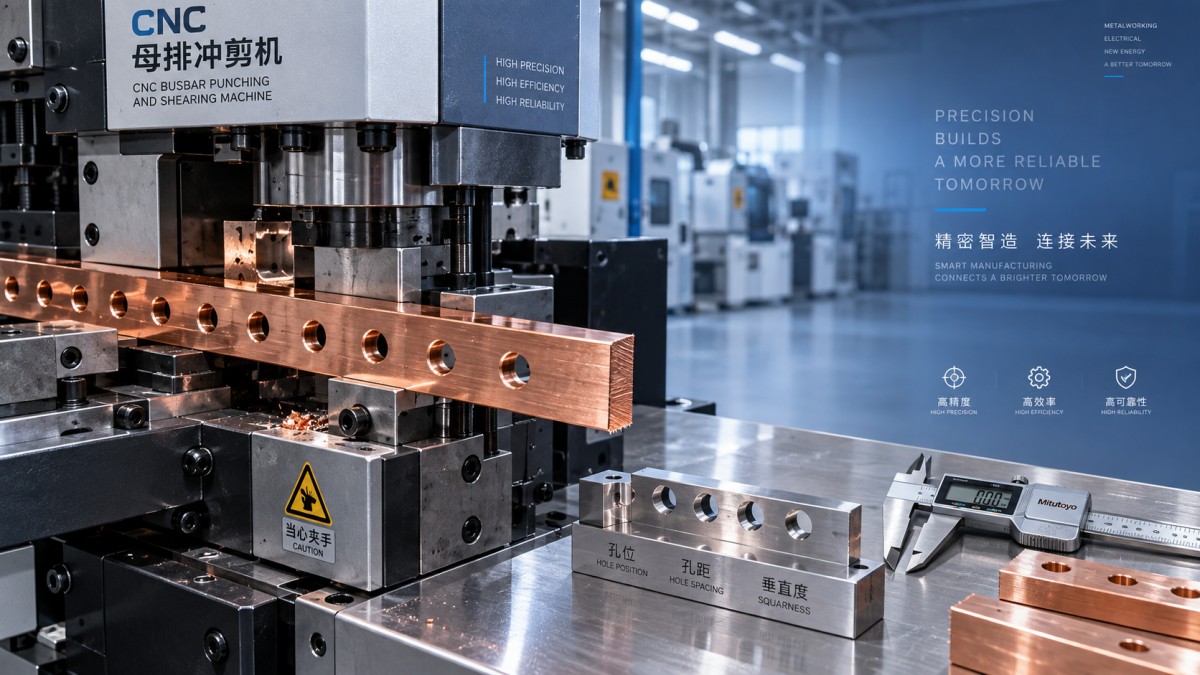
Hole location is usually the most sensitive punching tolerance because it governs whether busbar joints, insulators, terminals, and support brackets line up as designed. A hole may have the correct diameter but still create a poor connection if its centerline is shifted relative to the end of the bar, the bar edge, or another hole in the pattern.
The key inspection dimensions are normally the distance from the hole center to a datum edge, the distance from the hole center to the cut end, and center-to-center spacing across a pattern. QC procedures should use the same datum logic as the production drawing. Measuring each hole from whichever edge is convenient can hide cumulative error, especially on long distribution bars with repeated mounting positions.
A common mistake is to judge hole position only by whether a bolt can be inserted. Bolts may enter even when a joint is under lateral stress or the hardware is pulled off-center. In a completed panel, that offset can alter conductor routing or reduce intended clearance to nearby live parts. The acceptable positional tolerance should therefore be derived from the assembly drawing and the available clearance around the connection—not simply from bolt diameter.
Hole Size, Shape, and Tool Condition
Punch diameter matters for fastening clearance, but it should be assessed together with hole shape. A worn punch and die set can produce out-of-round holes, tapered walls, distortion near the edge, or pronounced burrs. These conditions can affect washer seating and create sharp points that remain hidden after assembly. Thin material may deform differently from thick copper or aluminum, so one inspection standard should not be assumed to suit every bar section.
Tool wear also changes gradually. That makes first-off inspection important, but not sufficient. A sensible control plan includes checks after defined production intervals, after a tooling change, and whenever operators see a change in punching force, noise, edge quality, or slug ejection. Exact inspection frequency should reflect batch size, material, tool history, and the consequences of a mismatch in the final assembly.
For busbar mold supply, replacement tooling should be matched carefully to the required hole geometry and material thickness. A listed Punch Die at $66 may be a useful reference point for basic tooling procurement, but suitability should never be judged by price alone. Die clearance, tool material, dimensional consistency, and compatibility with the machine’s tooling system all influence the finished hole.
Shearing Accuracy Is More Than Overall Length
Cut length is the first shearing result most shops record, and it is certainly important. A bar that is too long may interfere with barriers, enclosure walls, or neighboring conductors. One that is too short can force an awkward joint arrangement or leave insufficient overlap at a connection. But a length measurement alone does not confirm a good cut.
The squareness of the cut face is equally relevant. If the shear line is angled, the effective reference point at the bar end changes across its width. This can shift hole-to-end dimensions, make parallel busbars look uneven, and complicate stacked connections. On wider bars, even a modest lack of squareness becomes more noticeable during fit-up.
Burr height and edge deformation need separate checks. A small, controlled burr may be manageable where the design permits deburring, but loose material, sharp edges, or heavily rolled corners should not be dismissed as cosmetic defects. They can injure installers, damage insulation during handling, prevent flat seating at a joint, or concentrate stress near a bend. Aluminum deserves particular care because its surface can gall or distort under unsuitable tooling conditions.
Flatness, Twist, and the Relationship Between Operations
Punching and shearing do not occur in isolation. Clamp pressure, guide alignment, tool sharpness, and material handling can introduce local deformation. A busbar may meet its hole and length dimensions while failing to sit flat against a terminal pad. That is why receiving inspection of finished bars should include a fit-related view: does the part remain flat enough for its intended connection surfaces, and is there visible twist that could force the assembly during bolting?
This becomes more critical when punched parts are subsequently bent. The bend datum must relate correctly to the punched pattern. If the distance from a hole pattern to the bend line drifts, a terminal or support may no longer fall in its designed plane. A quality plan should track the whole dimensional chain rather than approve punching, shearing, and bending as unrelated operations.
Set Tolerances From Functional Risk, Not Habit
Production teams sometimes inherit a single “standard tolerance” for all busbars. This is convenient, but it can be misleading. The tolerance needed for a short cross-link with generous mounting slots is not necessarily appropriate for a long main busbar crossing several compartments. Similarly, a non-critical mounting hole should not be treated the same as a hole establishing the position of a power connection or insulating support.
A useful review separates dimensions into three groups:
- Functional dimensions that determine joint fit, support position, or electrical spacing.
- Controlled manufacturing dimensions that affect appearance, handling, and repeatability but have more assembly allowance.
- Non-critical dimensions that still require consistency, but do not justify extensive inspection on every part.
Electrical clearance and creepage requirements should be verified against the applicable switchgear design standard, voltage class, material system, and project specification. A processing machine cannot determine compliance on its own. It can, however, repeatedly produce the dimensions established by the design team, provided the datum setup, tooling, program control, and inspection methods are reliable.
What to Examine in a Busbar Punching and Shearing Machine
When evaluating a busbar punching and shearing machine, safety and QC personnel should look beyond nominal capacity. Repeatability of positioning, rigidity of the workholding arrangement, machine reference methods, tooling interchangeability, and accessibility for measurement all affect practical tolerance control. A machine that is fast but difficult to set from a consistent datum can create avoidable variation between operators or shifts.
It is also worth asking how the equipment handles copper and aluminum across the planned thickness range. Material behavior, punch load, and cut quality vary. Demonstrating a representative production part is generally more informative than reviewing a generic capacity claim. The test piece should include the actual hole pattern, end dimensions, and edge-quality expectations that matter in the panel design.
Founded in 2014, Dexinjia (DXJ™) manufactures CNC busbar processing equipment for bending, punching, cutting, and embossing of copper and aluminum bars. Its range includes 3-in-1 machines, CNC bending machines, and portable hydraulic equipment. For buyers building a controlled process, the relevant discussion is not merely machine configuration; it is how precision molds, stable drive components, setup support, and inspection practices can be aligned with the tolerances of a specific busbar drawing. DXJ states that its production follows strict quality control and that its equipment carries ISO, 3A, CE, and EAC certifications; project teams should still confirm which documentation and configuration apply to their intended market and installation.
A Practical Release Check Before Parts Reach Assembly
Before a punched and sheared batch is released, inspect more than a random overall length. Confirm critical hole locations from the approved datums, hole size and shape, center distances, cut squareness, burr condition, surface damage, and flatness where contact faces are involved. Compare the first-off part against a mating component or assembly fixture when possible. That simple fit check often reveals a dimensional interaction that isolated measurements miss.
The most dependable tolerance strategy is therefore functional rather than theoretical. Define the dimensions that protect electrical spacing and mechanical fit, establish a repeatable reference system on the busbar punching and shearing machine, maintain the punches and dies, and verify the finished part in the context of the switchgear design. That approach reduces rework without imposing unnecessary precision where the assembly does not need it.
Send Us A Message
Get in Touch
*We respect your confidentiality and all information are protected.

First class quality service and professional after-sales team.