



Reducing Copper Scrap with a Busbar Punching and Shearing Machine
Copper scrap is rarely caused by one dramatic failure. More often, it builds up through short offcuts, holes placed a few millimeters out of position, burrs that require a part to be rejected, or layouts that force an operator to trim material twice. In a distribution cabinet or transformer fabrication workflow, these losses become expensive because copper is both a high-value material and a frequent production input.
A properly selected busbar punching and shearing machine reduces scrap by controlling the sequence from marking to punching and cutting. The practical direction is straightforward: establish a repeatable part layout, punch features from reliable reference edges, cut only after critical holes have been verified, and maintain the dies and cutting tools that determine edge quality. Equipment improves consistency, but the largest material savings come from combining machine accuracy with disciplined job preparation.
Where copper waste usually starts
Scrap is often blamed on the cutting operation because the waste is most visible there. Yet the root cause may occur earlier. A busbar blank can be cut to the correct length and still become unusable when a hole pattern is offset, a bend allowance was omitted, or the wrong punch die was installed. Once holes or bends are formed, recovery options are limited; copper may be recyclable, but it no longer has the value of a finished conductor.
Several recurring conditions deserve attention:
- Unplanned cut lengths: Operators cut individual pieces from a stock bar without considering the next part in the job. The remaining length may be too short for the following requirement.
- Inconsistent datum selection: Measuring one hole from the left edge and another from a previously punched hole creates cumulative error, especially on longer bars.
- Late-stage correction: Cutting before checking the hole pattern can turn a correctable positioning issue into a rejected part.
- Worn or mismatched tooling: Dull shear blades, damaged punch dies, or an incorrect punch-and-die clearance can leave heavy burrs, distorted holes, or deformed edges.
- Drawings without process allowances: A finished dimension is not always the same as the starting blank length when bending or end clearances are involved.
The most useful way to evaluate waste is to separate unavoidable remnants from preventable rejects. A narrow piece left after nesting parts may be unavoidable. A full-length copper bar rejected because the first hole was referenced from the wrong edge is a process-control problem.
Plan the material before the machine starts
Before an operator loads copper onto the work surface, review the order as a group of parts rather than a series of independent cuts. Sort busbars by width, thickness, and required finished length. Then arrange cut lengths from the same stock size so that longer parts are considered first and short pieces are assigned to usable remnants where possible. This does not require complicated software for every job; even a clear cut list can prevent operators from turning suitable leftovers into random short offcuts.
The cut list should show more than length. Include material size, quantity, reference edge, hole locations, bend locations, and whether a dimension is measured before or after forming. Where identical parts are required, identify one approved first-off piece and keep it available for comparison during the run.
For parts that will be bent, establish the forming sequence before cutting a large batch. The required blank length depends on the bend geometry, tooling, and material thickness. Producing a small trial piece is often less costly than discovering after dozens of cuts that the formed busbar does not meet the installation dimension. This is particularly important where clearances inside a cabinet are tight or multiple bars must align with fixed terminals.
Use a stable reference for punching accuracy
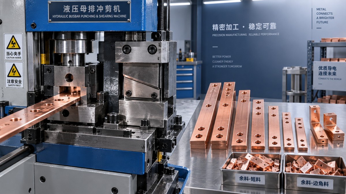
Hole placement is a major source of hidden scrap because an incorrectly positioned hole can compromise electrical connection, insulation clearance, or assembly alignment. Marking every location from a tape measure can work for occasional work, but it introduces variation between operators and makes repeat production slower. A fixed stop, guide, or clearly defined datum edge gives the process a repeatable starting point.
Measure all related holes from the same reference whenever the drawing permits. For example, a group of terminal holes should normally be located from one end or one side of the bar, rather than chained from hole to hole. This approach prevents small measurement deviations from accumulating across the part.
Before processing a production batch, verify four details on the first piece:
- Confirm the copper width and thickness match the selected tool and machine capability.
- Check the punch diameter against the drawing and the intended fastener or terminal hardware.
- Measure the center distance from the selected datum, not merely the visual position of the hole.
- Inspect both faces for excessive burr, deformation, or signs that the die clearance is unsuitable.
First-off inspection should happen before the remaining blanks are punched. This short pause protects a much larger quantity of material. It also gives the production team a chance to identify ambiguous drawing dimensions, wrong punch selection, or stop settings that have shifted during changeover.
Cutting quality affects whether a part remains usable
A clean shear is not only an appearance issue. A rough or distorted cut end may require deburring, reduce fit-up quality, or create a sharp edge that needs additional handling. When the damage is severe, the part may need to be shortened, which can make it unusable. Copper is comparatively soft, but thick or wide bars still place substantial load on the cutting system.
Maintain the cutting components according to their actual condition rather than waiting for obvious failure. Inspect for chipped edges, uneven wear, loose fasteners, and alignment problems. A machine that begins to produce an angled cut, a pronounced rollover, or a noticeably heavier burr should be checked before the issue is repeated across a full production order.
Material support matters as well. A long busbar that sags or twists during cutting can shift against the stop. Support the workpiece so it stays flat and square to the cutting line. Do not rely on hand pressure to compensate for an unstable setup; it is inconsistent and can create both quality and safety concerns.
Match capacity to the work actually being processed
Buying more tonnage than necessary does not automatically lower scrap. The more relevant question is whether the machine can process the planned copper sizes with stable control, suitable tooling, and a workflow that fits the production environment. A portable machine may be appropriate where cabinet parts are processed in smaller lots, work must move between stations, or copper and related metal components are handled in the same area.
For example, the DXJ-200A Portable Hydraulic Busbar Machine combines cutting, bending, and punching functions and is specified for copper and aluminum bars up to 200 mm wide and 3–12 mm thick. Its punch capacity covers Φ6 to Φ20.5, with standard dies listed as Φ7, Φ9, Φ10.5, Φ13.8, Φ17.5, and Φ20.5. Those dimensions should be checked against the actual busbar drawings and fastening requirements before a purchasing decision is made.
Its stated hydraulic outputs are 20T for cutting, 20T for bending, and 35T for punching. These values help indicate the machine’s intended processing range, but they should not replace confirmation of the exact material grade, thickness, tool condition, and operation. A practical benefit of a combined unit is that cutting, punching, and bending can be performed under one controlled setup approach, reducing the handoffs where part orientation or measurement references can be lost.
Arrange the sequence to protect the most valuable work
In many jobs, the preferred order is to punch critical features while the bar is still long enough to register firmly against a stop, inspect those features, then make the final cut. This leaves more options if a hole location needs correction before the finished length is established. However, the right sequence depends on the part shape. Short parts may be difficult to hold safely before punching, while some bend configurations require cutting first. The key is not a universal order; it is defining the order on the job sheet and keeping it consistent.
Where a part has both holes and bends, determine whether the holes are dimensioned from the unbent blank or from the finished formed edge. Confusing these two references creates a frequent and costly error. Mark the datum clearly, and use a sample part to verify that the bend does not move a connection hole away from its intended assembly position.
Control the small losses that become routine
Scrap reduction also depends on what happens between jobs. Separate usable copper remnants by width and thickness, label their actual lengths, and protect them from being mixed with unidentified material. A clean remnant rack makes it possible to use suitable pieces for short links, jumpers, or compact cabinet bars without guessing their dimensions.
Record rejection reasons in simple categories such as wrong length, incorrect hole location, burr, bend error, or surface damage. The purpose is not paperwork for its own sake. After several production cycles, repeated categories reveal whether the main issue is cutting layout, drawing interpretation, tooling condition, or operator setup. That evidence is more useful for improving material utilization than treating all discarded copper as unavoidable waste.
A busbar punching and shearing machine becomes most effective when it is part of a controlled production method: planned cut lengths, one reliable datum, first-piece verification, maintained tools, and documented processing order. These practices reduce preventable scrap while helping finished copper busbars arrive at assembly with cleaner edges, correct hole patterns, and fewer last-minute adjustments.
Send Us A Message
Get in Touch
*We respect your confidentiality and all information are protected.

First class quality service and professional after-sales team.