



How to Diagnose Positioning Errors on a 3 in 1 CNC Busbar Machine
How to Diagnose Positioning Errors on a 3 in 1 CNC Busbar Machine
Accurate positioning is what separates a clean busbar from a costly remake. On a 3 in 1 CNC busbar machine, a few millimeters of error can leave punched holes off-center, bend lines shifted from the drawing, or cut lengths that no longer match the assembly requirement. The machine may still run smoothly, which is why positioning faults are often misdiagnosed as “CNC problems” when the real cause is a loose datum, worn tooling, material variation, or an incorrect program reference.
The fastest way to troubleshoot is not to adjust every setting at once. Start by identifying whether the error is repeatable, whether it appears in one operation or all operations, and whether it changes with material size. Those three observations usually narrow the search considerably.
Read the Error Pattern Before Touching the Machine
A repeatable error is different from a random one. If every hole is consistently 2 mm too far from the leading edge, the likely issue is a program datum, feed reference, or offset value. If the first hole is correct but later holes gradually drift, look more closely at feeding accuracy, clamp slip, encoder feedback, or backlash in the moving system.
When punching, bending, and cutting are all shifted by approximately the same amount, the fault is often upstream of the individual workstations. The material may not be seated against the reference stop, the zero point may have been set incorrectly, or the machine may be reading the wrong starting edge. By contrast, if cutting remains accurate but bending is wrong, there is little reason to begin with the feeding axis. Check the bending die, punch position, bend allowance setting, and the selected tooling data first.
Operators sometimes judge a result against the busbar’s raw edge without checking whether that edge is square. A sheared or manually cut starting edge can be uneven. If the CNC program assumes a true reference edge but the workpiece begins with a skewed edge, measurements taken from one corner may suggest a machine error that does not actually exist.
Confirm the Material Datum and Clamping Condition
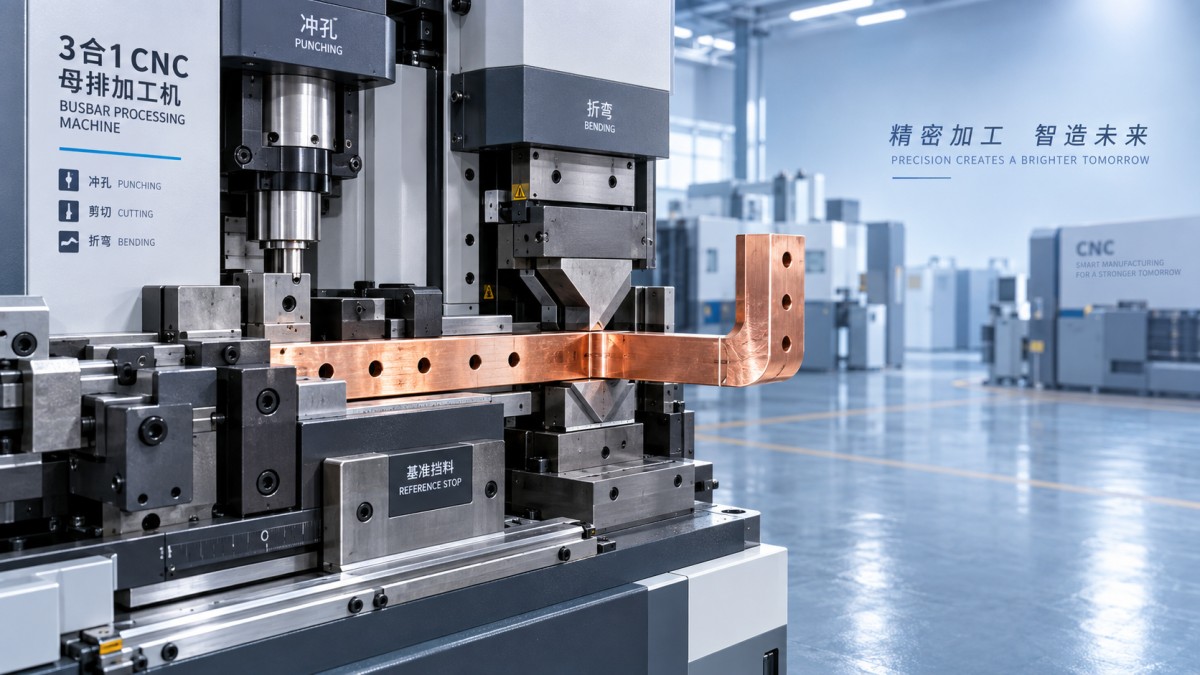
Before checking software, inspect how the copper or aluminum bar enters the machine. It should sit flat on the support surface, contact the designated locating stop, and remain securely held during feed and processing. A thin layer of oil, burrs on the edge, oxide buildup, or chips beneath the bar can lift the workpiece enough to affect both hole location and bend quality.
Clamp marks are useful clues. If they are light, uneven, or appear to move between parts, the material may be slipping under feed force. This is more common with smooth aluminum busbar, narrow strips, or sections with surface contamination. Do not simply increase clamping pressure without considering the material condition and clamp-pad condition. Excess force can mark soft copper, while worn or hardened pads may still fail to grip consistently.
Also compare the actual bar width and thickness with the program. A nominal size is not always the size being processed. If the tooling or machine parameters were created for one thickness but the job uses another, bend geometry and side reference positions can change. This is especially noticeable where a hole pattern must align closely with a subsequent bend.
Separate Tooling Errors from CNC Position Errors
A worn punch and die set does not normally move a programmed hole location, but it can make the result look misplaced. Excessive punch-to-die clearance may create a heavy burr or a distorted hole edge. If the punch is chipped, bent, or not centered over the die opening, the hole can be visibly biased to one side. Measure from the intended datum to the actual hole center rather than judging by the burr outline.
For bending, inspect the die shoulders, bending punch, guide surfaces, and retaining bolts. Any looseness in the tooling stack can alter the bend line under load. A machine may position correctly in an unloaded dry run yet shift when the punch contacts a thick copper bar. That is why a meaningful check includes both an air movement test and a controlled test piece.
Use a short sample with one simple operation whenever possible: one cut, one hole, or one bend from a known reference edge. Complex programs make diagnosis slower because several offsets and stations are involved. If the simple test is correct, the problem is more likely in the part program or operation sequence than in the machine’s basic positioning system.
Check Program References, Offsets, and Operation Sequence
Many positioning complaints begin after a program edit, a tooling change, or a switch to a different busbar size. Confirm that the program uses the intended reference: leading edge, trailing edge, centerline, or side edge. A part drawing may dimension holes from the left end, while the operator loads the bar from the opposite direction. The result can be a perfectly executed but completely wrong pattern.
Review tool offsets after replacing punches, dies, blades, or bending molds. The physical dimensions of replacement tooling may not be identical to the previous set, even if the tooling designation is the same. A reliable practice is to record verified offsets with the tool ID and confirm them after maintenance rather than relying on memory or old job notes.
Operation order matters as well. Punching after a bend can be appropriate for some designs but may complicate positioning if the formed part no longer sits flat against the locating system. Similarly, a cut made before later operations changes the available reference length. If a job was originally programmed around a different sequence, the coordinates need to be reviewed rather than copied unchanged.
Look for Mechanical Play and Feedback Problems
If the error varies from part to part, mechanical movement deserves close attention. Check feed rollers, guide rails, ballscrews, couplings, drive belts where fitted, and fasteners around the moving carriage. Backlash often appears when the axis changes direction: a position may be correct when approached from one direction and wrong when approached from the other.
Watch the machine during slow manual movement. Unusual noise, hesitation, vibration, or a delay between motor motion and carriage movement is not normal. On CNC equipment, encoder or sensor faults may also cause lost position information. These checks should follow the manufacturer’s maintenance and electrical safety procedures; do not bypass interlocks or probe electrical components casually during production.
Machines built with rigid frames, precision molds, and stable drive components reduce the risk of recurring drift, but no processing machine is immune to wear, contamination, or incorrect setup. For this reason, a scheduled reference-point verification is more useful than waiting until scrap appears.
A Practical Verification Routine
After correcting a suspected cause, do not immediately return to a full production batch. Run two or three sample pieces from the same material lot and measure each from the same datum. Check the first and last feature, not only the feature nearest the start edge. This reveals whether the correction solved a fixed offset or merely hid an accumulating feed error.
- Verify the raw material is flat, clean, and seated against the intended stop.
- Confirm actual width and thickness before selecting or editing a program.
- Inspect punch, die, bending mold, and blade alignment before changing CNC values.
- Use one simple test feature to establish whether the error is fixed or variable.
- Save confirmed offsets and document the tool set used for the job.
For workshops producing switchgear components, transformer connections, or electrical distribution assemblies, busbar accuracy is only one part of the process chain. Where coil and conductor work are handled in the same facility, repeatability in each station matters. Equipment such as the DXJ-RX800 Automatic Toroidal Coil Winding Machine uses CNC-controlled laying and stated 0.01 mm laying accuracy, illustrating the same practical principle: reliable output starts with a stable reference, controlled material handling, and settings that match the real workpiece.
When the Fault Needs Technical Support
If positioning remains inconsistent after confirming material setup, tooling, program coordinates, and visible mechanical components, stop compensating with repeated manual offsets. Constantly changing the program to chase a drifting error can create a second problem and make later service more difficult. Record the material specification, program version, tooling used, measured deviation, and whether the error changes by direction or distance.
That information gives a service technician something concrete to evaluate. Manufacturers such as Dexinjia, which has produced CNC busbar processing equipment since 2014, typically see the same core causes repeatedly: incorrect datum selection, poor clamping, mismatched tooling data, and feed-system wear. A methodical diagnosis usually restores accuracy faster than replacing parts blindly—and prevents the next batch of copper or aluminum busbar from becoming expensive scrap.
Send Us A Message
Get in Touch
*We respect your confidentiality and all information are protected.

First class quality service and professional after-sales team.