



Quality Control Points for Punching, Cutting, and Bending in One Machine
A combined punching, cutting, and bending machine can reduce handling time, but it also concentrates several defect risks in one process. A part that passes an individual punching check may still fail after bending because the hole position shifts relative to the datum, a burr cracks the bend area, or the bend angle changes the required electrical clearance. For quality inspectors and safety managers, the control plan must therefore assess the finished busbar, not three isolated operations.
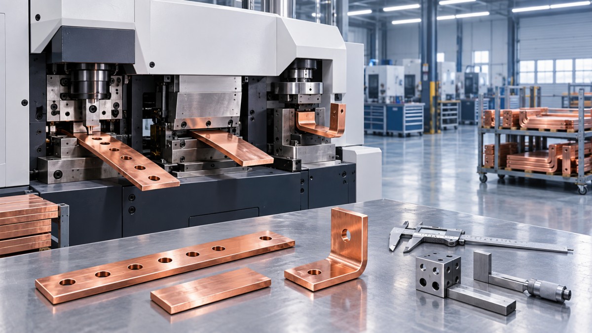
For a 3 in 1 cnc busbar machine, the most important inspection points are material condition and datum control before processing, dimensional relationship between holes, cut edges, and bends during production, and machine guarding and tooling condition throughout the shift. Stable results depend as much on setup discipline and tool maintenance as on CNC program accuracy.
Start with the Material and Reference Datum
Copper and aluminum busbars should be identified by grade, width, thickness, temper, and surface condition before entering the machine. These properties affect punching force, burr formation, cutting deformation, and the achievable bend radius. Treating material of the same nominal size as interchangeable can create inconsistent results, particularly when a bending program was established using one temper and production later uses a harder or softer batch.
The surface also deserves attention. Oxidation, scratches, embedded debris, or protective-film remnants can affect clamping and leave marks that become problematic in visible panels or high-contact electrical joints. For coated or plated busbars, the inspection plan should define whether coating damage is acceptable around holes, cut faces, and bend zones before production begins.
Datum selection is the next control point. Hole patterns and bend locations should be measured from a defined physical edge or end, rather than from whichever feature was processed first. A cut-length variation at the start of the workflow can otherwise move every downstream feature. Operators should confirm that the material is seated against the correct stop and that the programmed origin matches the drawing datum, especially after a change in busbar width, thickness, or fixture arrangement.
Inspect Punching as a Functional Feature
Punched holes are often evaluated only by diameter and visual appearance. That is insufficient for busbars that must align with terminals, insulators, panel openings, or joining hardware. Hole position, center-to-center spacing, edge distance, and the relationship of each hole to the future bend line all need defined acceptance limits.
A practical first-piece inspection should check the full hole pattern against the drawing before the batch continues. Where several hole sizes or slots are present, verify that the correct punch and die set was installed, not simply that a hole exists in the expected location. Similar-looking tooling can create a defect that remains undetected until assembly.
Burr control is equally important. Excessive burrs can interfere with contact surfaces, create sharp-edge hazards, damage insulation, or initiate cracking when the hole lies near a bend. Inspect both punch entry and exit faces. A clean-looking entry face does not prove that the exit side is acceptable.
- Check hole diameter or slot width with suitable gauges or calibrated measuring tools.
- Measure hole location from the approved datum and confirm edge distance.
- Examine burr height, rollover, deformation, and partially sheared edges.
- Confirm that holes near bends satisfy the specified clearance from the bend line.
- Record first-piece results after tool changes, program changes, or material changes.
Tool wear often reveals itself before a punch fails completely. Increased burrs, uneven hole walls, higher operating noise, material distortion, or a rising need for manual deburring are useful warning signs. Continuing production after these symptoms appear may save a setup interruption while producing a larger sorting and rework problem downstream.
Cut Quality Affects Both Assembly and Safety
Cutting is sometimes treated as the lowest-risk station because length is easy to measure. In practice, cut-face squareness and edge condition can be as consequential as nominal length. An out-of-square end may prevent a busbar from seating flat against a terminal or may reduce the intended contact area. A heavily burred edge creates a direct handling hazard and can damage sleeving, heat-shrink material, or adjacent insulation during installation.
Inspect cut length from the same datum used by the part drawing. Also check for twist, local bowing, and end deformation. These conditions are especially relevant for narrower sections, long parts, and aluminum busbars, where handling and clamping can influence flatness.
The acceptance standard should distinguish a light, controllable edge condition from burrs that require secondary finishing. If deburring is needed, it should be a defined process with a clear inspection requirement. Uncontrolled manual filing can alter dimensions, round functional corners, and introduce inconsistent surface conditions between operators.
Bending Must Be Verified in Relation to Earlier Features
A bend angle by itself does not determine whether the busbar is usable. The inspector should assess angle, inside bend radius, leg lengths, flatness, and the position of punched features after forming. The finished geometry determines whether the part will fit in its enclosure without forcing, stressing terminals, or violating required clearances.
Springback varies with material properties, thickness, bend direction, and tooling condition. The CNC compensation value should therefore be validated whenever the material specification changes or a new tooling set is introduced. A previously approved program is not permanent proof of conformity when these inputs have changed.
Look closely at the outer bend surface for cracks, whitening, deep scoring, or plating damage. Copper and aluminum may respond differently to the same bend setup. A bend radius that is acceptable for one material condition may be too tight for another. Where the drawing defines a minimum radius, the production setup should be checked against it directly rather than relying on visual judgment.
Control the Machine Condition, Not Only the Parts
Part inspection detects defects; machine-condition checks help prevent repeated defects. Before production and at defined intervals, confirm punch and die condition, cutting blade condition, bending die alignment, clamp performance, lubrication where applicable, and the integrity of stops and locating surfaces. Loose fasteners, worn guides, or damaged dies can produce gradual dimensional drift that is difficult to identify from occasional visual checks.
Safety controls belong in the same routine. Guards, interlocks, emergency stops, foot controls, hydraulic connections, and work-area housekeeping should be checked before operation. Punching and cutting produce sharp offcuts, while bending creates pinch points and stores mechanical or hydraulic force. A quality plan that encourages operators to reach into a working area to clear scrap is also a safety failure.
Production records should connect the part batch with the material lot, program revision, tooling used, first-piece result, in-process checks, and any adjustment made. This does not need to become excessive paperwork. Its value is in distinguishing an isolated defect from a process shift and in preventing an unapproved parameter change from becoming the new normal.
In transformer manufacturing, busbar inspection should also remain separate from coil-winding acceptance criteria. Equipment such as the DXJ-RX800 Automatic Toroidal Coil Winding Machine addresses winding accuracy and tension control, while busbar processing requires its own dimensional, edge-quality, and forming checks. Keeping these criteria distinct makes final assembly issues easier to trace to the correct process.
The strongest control point is a finished-part inspection that follows the busbar’s installation function: will it locate correctly, make a clean electrical connection, maintain required spacing, and be safe to handle? When punching, cutting, and bending are evaluated as one connected geometry, inspectors can catch the defects that isolated station checks often miss.
Send Us A Message
Get in Touch
*We respect your confidentiality and all information are protected.

First class quality service and professional after-sales team.